Geometry for Computer Graphics
Introduction to Geometry for Computer Graphics
In this article we're going to look at some of the basic geometric constructs we commonly use in computer graphics, with an emphasis on those for real-time graphics and games. Geometry is a large and exciting topic, but we're only going to touch on a few interesting aspects in this intro article.
When we're making a CG scene, be it for a game or an offline render, we usually want it to include some objects which may or may not have real-world-like properties. The way we represent our shapes in our virtual world will have an impact in what we're able to achieve and how fast it can be drawn or manipulated.
Let's consider two choices in how we represent geometry (there are more, but let's start with these two). We can describe an object using a set of points and polygons, which we refer to as a mesh. Or we can use a mathematical equation, such as expressing a sphere as a centre point and a radius then using maths to find the surface or volume as needed.
Each approach has advantages and disadvantages:
- Points and Polygons:
- These can be hardware accelerated by the graphics card so they're really quick to draw
- Transparent materials and materials with internal structures are difficult to represent. How can we draw smoke? Or a glass marble?
- There are accuracy issues for curved surfaces. No matter how many triangles you use, the underlying geometry will always be faceted. There are rendering tricks we can use to hide some of this, but silhouettes are usually a problem.
- Maths:
- The graphics card is terrible at handling these (at the moment) so they're really slow to draw.
- Some mathematical methods can work well with transparent materials and insanely complex geometry.
- There are no mathematical limits on accuracy, just practical computational ones like the limits of a floating point number.
In reality, both approaches have their use in games and graphics.
For most rendering tasks, points and polygons currently win. This is not likely to change in the short-term, but as graphics hardware gets more powerful we are gradually seeing more exciting things in this area so it's just a matter of time.
The maths approaches are great for describing simple shapes such as spheres. We can use these as primitive shapes for collisions as the intersection calculations are significantly easier than if we were to describe two spheres with meshes and perform thousands of triangle-triangle intersections.
How we apply these different approaches are both important and interesting aspects of computer graphics.
Points
Points are the fundamental building block for meshes and are very important in how we define geometry that is destined for the graphics card.
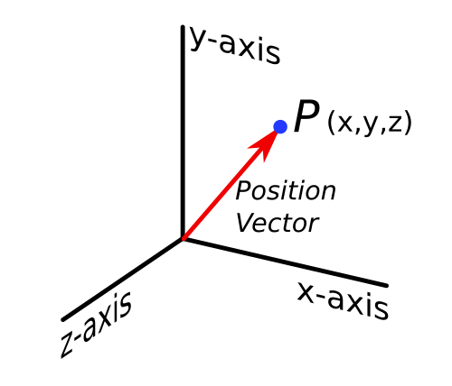 Mathematically we can define a point in space using its coordinates, (x,y,z) in a 3D Cartesian system. We can also use a position vector for this, which is a subtle but important shift in thinking. The conceptual use of a vector means we can transform points to wherever we want. This basically means we can move our objects around in space, and we'll be using matrices to do this.
It's important to realise though that a position by itself might not be enough information. For example, perhaps we want to associate each point with a colour too. Or maybe some other property. Our actual definition then needs to be expanded to include a collection of different attributes, though the position in space remains the most important.
Point Clouds
I hesitate to put this in the 'geometry' article but point clouds are important and useful. They're basically a collection of points in 3D space, are often generated by 3D scanners and frequently have colour information too.
Mostly there's not a lot you can do with a point cloud by itself, we normally have to convert them into something else. Unfortunately there are a whole range of problems with this type of data, which are mostly to do with how it was captured:
- It's common to have artefacts and noise which can distort the shape. Most visual-based (including laser) 3D scanners have difficulty coping with very reflective and very dark surfaces. They just can't tell where the surface is supposed to be, which can result in recorded positions that are well above or below their actual position (or sometimes they're simply missing).
- Scans of objects are usually done in multiple parts, which each result in a separate dataset. To reconstruct a complete model we have to 'stitch' these separate datasets together, which may include overlaps and missing parts.
- Once we have a 'complete' point cloud, we normally need to convert it into a full mesh. This is a potentially complex problem, but there is lots of research in this direction nowadays and we have some reasonable methods.
Lines
 It's worth starting with some definitions here. In mathematics, a line will extend infinitely. If we have two points and wish to define a line between them, this is known as a line segment. A line segment has no fixed start or end point. If we need this, we will call it a directed line segment and the start point is usually called the tail and the end point is usually called the head. A vector between two points is an example of a directed line segment.
Algebraically, we define a line in 2D with the equation y = mx + c, where m is the gradient and c is the y-intercept.
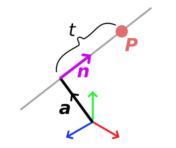
We can also define a line using vector notation, where a specific point on the line p is given by p = a + tn, where a is a position vector to a point on the line, n is a unit vector defining the direction of the line and t is a scalar that defines the distance from a to p in the direction of n.
The vector notation of a straight line is quite important and can appear in a variety of different places. For example, if you're building a ray tracer it's the form you'll most likely use to describe a ray (though here, a is usually the origin of the ray and it doesn't make sense to consider negative values of n).
Curves
Curves are very important for computer graphics. Some 3D modelling operations rely on them. You'll see them in 2D vector or raster graphics libraries and programs (E.g. Inkscape, Illustrator, Photoshop).
Curves are also very important for things like animation. They are used to define the motion paths for objects and cameras, to describe how their positions and properties change over time.
To allow curves to be used for all of these different tasks, it's important that our artists can control them. This element of artistic control is a very important one in computer graphics and one that's often overlooked by technically-focussed people so it's worth keeping in mind.
Bezier Curve
These are a common and useful way of expressing curves using end points and control points. Until I get diagrams and full maths notation up and running there's probably not much point talking about these in any depth, but it's useful to know they exist. I think they deserve their own article anyway.
2D Shapes
There are various different 2D shapes and properties that we could discuss, but these are mostly early maths concepts and I want to point out a few issues with polygons and triangles.
For lines, or specifically line segments, we took the concept of a point and connected two of them together. The whole idea of 2D shapes is that we extend this further to connect many points so that they form a surface. Such a surface is called a polygon.
While we can define these 2D shapes in 2D space, more interesting things happen when we work in 3D space. If we connect, say four points together, they will form a four-sided polygon. In 2D space this is quite a well behaved shape, but in 3D space an important question to ask is whether they are all on the same plane. I.e. if you describe a plane in space, do all the points sit on the plane, or are some higher than others?
If the points are not on the same plane, we would say it is non-planar, and it's potentially a bit of a problem. Given the information of just the points and their connections, there's no easy way of defining where the surface actually lies. With a four-sided convex polygon this will typically take one of two forms with a straight part between opposing corners.
Triangles are wonderful little creatures. Triangles don't suffer from this problem. If you define three points in space they can only ever be on the same plane.
To get around the ambiguity of non-planar polygonal shapes, the graphics card will only work with triangles. In the past we could send polygons to the graphics card, but internally it would triangulate them. The difficulty with triangulation approaches is that there are many ways to achieve it. When it comes to triangulating an artistic model, especially one that needs to be animated, this can potentially cause a problem. If the triangulation goes in the wrong direction we can end up with quite nasty looking shapes. This is why I always advocate that it's best for the artist to decide how they want their geometry triangulated. They know how their model needs to bend and flex, so are far better placed to decide what would look best.
Transformations
Once we have defined a set of shapes, it's usual to want to move them around in some way. It's worth looking at some definitions and classifications before we look at the maths for these transforms:
Rigid (Isometric) Transformations
- Translation -e.g. moving something from side-to-side
- Rotation
- Reflection - an operation that produces a mirror-image copy
Similarity Transformations
- The above rigid transformations
- Plus, uniform scale - i.e. growing or shrinking something by the same amount in every dimension
Affine Transformations
- All the above similarity and rigid transforms
- Plus non-uniform scale
- Shear
Projective Transformations
- All the above affine, similarity and rigid transformations
- Plus projection - this is like a slide projector that projects the geometry at an angle to the screen
Transformation Properties
It's then interesting to plot which transformations preserve which properties:
| Distance | Angle | Ratios of Distance | Parallel Lines | Collinearity | |
|---|---|---|---|---|---|
| Rigid | Yes | Yes | Yes | Yes | Yes |
| Similarity | No | Yes | Yes | Yes | Yes |
| Affine | No | No | Yes | Yes | Yes |
| Projective | No | No | No | No | Yes |
Ratios of distance - the modpoint of a line segment will remain the midpoint after the transformation
Collinearity - all points that start in a line will still be on a line after the transformation
These transformations cover pretty much all we need for making games and most graphics applications. Fundamentally, all of the above transformations can be expressed as matrices. I will cover this in a future article.
3D Shapes
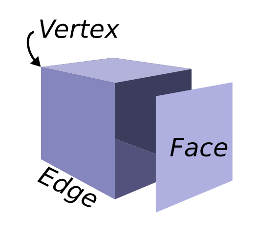
We assemble 3D shapes by piecing together 2D polygons - preferably triangles. To make them appear solid we make sure the corners match and there are no gaps.
Each flat 2D polygonal surface is called a face. A shared side where two faces meet is called an edge. The corners where multiple faces meet are called vertices.
The important thing to realise about this setup is that an 'object' here is not a solid thing at all. It's just a collection of surfaces and it's only when we make sure there are no gaps between them that we achieve the illusion of a solid 3D shape. For computer graphics and games this is fine and actually you'll find it's common to remove faces that we know we'll never see - if you look at the breakdown of film effects you'd surprised at how much geometry is missing.
This way of describing an object, with just its outer shell, is known as a boundary representation (or b-rep).
While this approach works well for graphics, where fewer faces means faster rendering times, it doesn't work well for other applications like 3D printing. For a 3D printer, we need to know about a real and solid shape. It's too easy to make mistakes and take shortcuts with b-reps. They can have holes and intersections that might look ok when rendered but make it difficult to tell where the exterior of an object ends and the interior begins. This doesn't make life easy for the software that interprets the 3D model and controls the 3D printer. It needs to know where to deposit material. It needs to know the actual interior volume of the object. But I'll save that for another article.
Conclusion
This article has been a gentle introduction to some exciting geometric concepts in computer graphics. We've barely scratched the surface of the topic but already there are some important points I suggest you take away:
- We use a position vector to define a vertex (a point in space).
- Triangles are great. You gotta love triangles. We use three vertices (i.e. position vectors) to define a triangle.
- A model / object / mesh (lots of words for the same thing really) is made up of lots of triangles. This means a mesh is a collection of position vectors.
- The different types of transformation. These cover all the common ways of manipulating an object (not modelling it, I mean when an object is completed and we want to move it around our game world). It's important to realise all these transforms can be expressed with a matrix. Since we can use a matrix to change a vector we can use a transformation matrix to move our models.